![]()
IoT Unlocked: Your Journey to Innovation Starts Now
![]()
IoT Unlocked: Your Journey to Innovation Starts Now

This blog post I will guide you through How to Control LED Over the Internet with Raspberry Pi Pico W Using Dweet.io, a simple and effective platform for IoT developers. In the world of IoT (Internet of Things), the ability to control devices remotely over the internet has become increasingly popular.
Raspberry Pi Pico W is a microcontroller with built-in Wi-Fi, opens a lot of possibilities for IoT projects, including the ability to control devices from anywhere in the world.
To complete this project we need some very basic components, which I believe you have it already.
Before diving into the code, ensure your Raspberry Pi Pico W is set up with the latest version of its Firmware you have already installed and running. If you are setting Raspberry Pi Pico W for the first time, I suggest you to go through this detailed step by step guide: How To Get Started with Raspberry Pi Pico in 2024.
Insert the LED into the breadboard. Connect the long leg (anode) of the LED to GPIO 0 of the Pico W through a 220-ohm resistor. Then, connect the short leg (cathode) directly to one of the ground (GND) pins on the Pico W.


import network
import sys
import time
import requests
import json
from machine import Pin

wlan = network.WLAN(network.STA_IF)
led = Pin(0, Pin.OUT)

def connect_to_wifi():
    wlan.active(True)
    for _ in range(10):
        if not wlan.isconnected():
            print("Connecting to the network...")
            wlan.connect("YOUR_SSID", "YOUR_PASSWORD") # Make sure to provide your WiFi credentials here
            time.sleep(2)

        if not wlan.isconnected():
            print("Cannot connect to the WiFi, please check your credentials")
            sys.exit(0)
    print("Connected to IP: ", wlan.ifconfig()[0])


def call_api():
    if wlan.isconnected() == True :
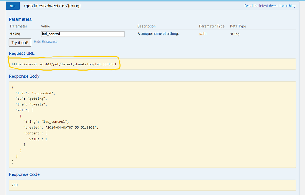
        response = requests.get("https://dweet.io:443/get/latest/dweet/for/led_control")
        data = json.loads(response.content)
        led_command = data["with"][0]["content"]["value"]
        print(led_command)
        led.value(led_command)

connect_to_wifi()
call_api()

while True:
    if wlan.isconnected() == True:
        call_api()
    else:
        print("Something went wrong, please try again")
        sys.exit(0)
    time.sleep(1)
network: Provides functionality for network-related operations.sys: Offers access to some variables used or maintained by the Python interpreter and to functions that interact with the interpreter.time: Provides various time-related functions.requests: Allows sending HTTP requests.json: Enables encoding and decoding JSON data.machine.Pin: Allows interaction with the GPIO pins on the microcontroller board.wlan: Initializes a WLAN (Wireless Local Area Network) interface, which is used to connect the microcontroller to a Wi-Fi network.led: Initializes a Pin object for controlling the LED. Pin 0 is specified as the pin number, and Pin.OUT indicates that it’s configured for output.connect_to_wifi(): This function is responsible for connecting the microcontroller to the Wi-Fi network. It attempts to connect to the specified Wi-Fi network (SSID and password) and retries up to 10 times if unsuccessful. If the connection fails after 10 attempts, the script exits.call_api(): This function is used to fetch the latest LED control command from Dweet.io. It sends an HTTP GET request to the Dweet.io URL, retrieves the response, parses it as JSON, and extracts the LED control value from the response data. Finally, it sets the LED state based on the received value.connect_to_wifi(): The script first attempts to connect to the Wi-Fi network by calling the connect_to_wifi() function. If successful, it prints the IP address obtained from the network configuration.call_api(): It then calls the call_api() function to fetch the LED control command from Dweet.io and control the LED accordingly.call_api() function to control the LED. If not, it prints an error message and exits the script.Save the file name as “main.py” into your Raspberry Pi Pico W device and click on Run.
Now go to dweet.io and click on created thing Post request and try to change the value to 0 and click Try it out. You will see LED would be turned off.
Using Dweet.io with your Raspberry Pi offers a simple and low-cost solution for getting started with IoT applications. This setup provides a robust foundation for more complex projects like home automation systems, allowing you to control various devices remotely.
If this guide really helped you and saved some time, consider buying me a coffee! Your support not only fuels my late-night coding sessions but also encourages me to create more helpful content like this. Simply click here or scan QR code to treat me to a cup. Thank you for your generous support!

Dweet.io is a simple cloud-based messaging service for IoT devices. It allows you to send and receive messages (or “dweets”) from your IoT devices using a simple, URL-based API. Devices can publish data to Dweet.io, and other devices or applications can retrieve the data using the unique name or identifier of the device.
The principles demonstrated here can be applied to a wide range of electronic devices, allowing you to control anything from motors to lights, as long as they are connected to the Raspberry Pi.
This project is compatible with any microcontroller that supports Python and has network capabilities, such as the ESP8266 or ESP32. These boards are widely used in IoT projects due to their built-in Wi-Fi modules.
Check the Wi-Fi signal strength in the area where your device is located. If the signal is weak, try moving the device closer to the router or using a Wi-Fi extender. Additionally, ensure that the Wi-Fi network is not overly congested and check for firmware updates for your microcontroller board that might improve network stability.
To control multiple devices, you can expand the GPIO initialization to include more pins. Adjust the call_api() function to handle different commands for different devices. For example, you might use separate Dweet.io topics for each device or encode multiple commands in a single JSON message.