Official Logo

IoT Unlocked: Your Journey to Innovation Starts Now
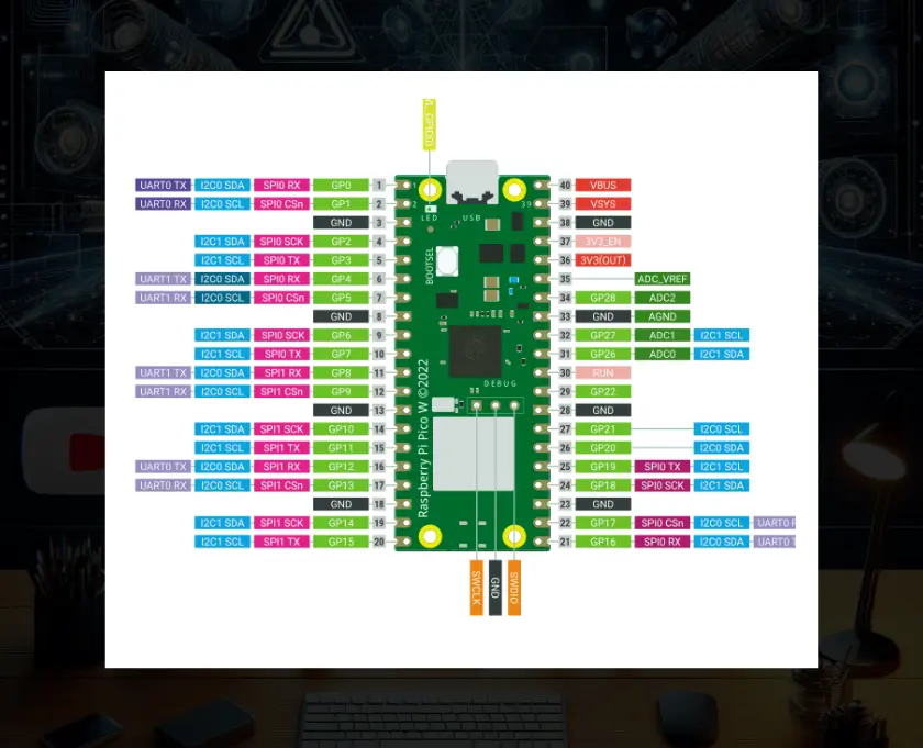
Raspberry Pi Pico W Pinout Explained: A Detailed Guide with Practical Examples

Raspberry Pi Pico W Pinout Explained: is essential for anyone looking to maximize the functionality of this powerful microcontroller. The Raspberry Pi Pico W offers a wide range of functionalities through its versatile pin configuration.

Understanding the pinout of the Raspberry Pi Pico W is crucial for leveraging its full potential in various projects. This guide provides a detailed explanation of each pin along with practical examples of their usage.
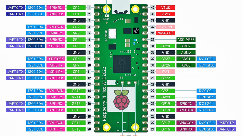
Understanding the Raspberry Pi Pico W Pinout

Understanding the Raspberry Pi Pico W Pinout

The Raspberry Pi Pico W comes with a rich set of pins, including GPIO, power, and special function pins. Here’s a comprehensive table summarizing the pin functionalities and examples of their usage:

PinDescriptionExamples of Usage
3V3(OUT)3.3V OutputPowering low-voltage sensors, Supplying power to 3.3V modules, Powering LEDs, Feeding power to external logic circuits, Providing a reference voltage for ADC
VSYSExternal Power Input (1.8V to 5.5V)Powering the board with a battery, Using an external power adapter, Supplying power from another microcontroller, Connecting to a solar power supply, Providing power from a USB port
VBUSUSB Power Input (5V)Powering the board directly from USB, Charging a battery connected to VSYS, Powering USB peripherals, Supplying 5V to external components, Powering an external display
GNDGroundCompleting the circuit for sensors, Grounding external components, Providing a common ground for multiple boards, Shielding for noise reduction, Grounding LEDs and resistors
GP0 – GP22General-Purpose I/O PinsDigital input from buttons, Digital output to LEDs, PWM output for motor control, Reading analog values via ADC (specific pins), SPI communication
GP23, GP24, GP25Special Functions (LEDs, WiFi, etc.)Onboard LED control (GP25), WiFi chip enable (specific to Pico W), Debugging with serial output, UART communication, I2C communication
TX, RXUART0 TX & RX (Serial Communication)Connecting to a GPS module, Serial communication with a PC, Communicating with other microcontrollers, Interfacing with Bluetooth modules, Debugging via serial monitor
SDA, SCLI2C Data and Clock LinesConnecting to an I2C LCD, Reading data from a temperature sensor, Interfacing with an EEPROM, Connecting to a real-time clock (RTC), Communicating with multiple I2C devices
MISO, MOSI, SCK, CSSPI Communication LinesInterfacing with an SPI display, Communicating with an SD card module, Connecting to an SPI-based sensor, Interfacing with a flash memory chip, Communicating with an external DAC
ADC0, ADC1, ADC2Analog to Digital Converter PinsReading a potentiometer, Monitoring a battery voltage, Reading an analog temperature sensor, Interfacing with an analog joystick, Reading light intensity from a photocell
RUNReset InputConnecting to an external reset button, Automating resets via a microcontroller, Integrating with a power management circuit, Using for firmware update triggering, Resetting during development/debugging
DEBUG (SWCLK, SWDIO)Debug InterfaceProgramming with a SWD debugger, Real-time debugging and monitoring, Flashing firmware, Profiling performance, Debugging low-level issues
USB D+ and USB D-USB Data LinesImplementing USB communication for data transfer, Using the board as a USB device (e.g., keyboard, mouse), Connecting to a USB host for firmware updates, Interfacing with USB peripherals (e.g., USB storage), Implementing USB-based serial communication
GP26 – GP28GPIO/ADC PinsReading analog values from a joystick (ADC input), Interfacing with a soil moisture sensor (ADC input), Measuring light intensity using a light sensor (ADC input), Temperature monitoring using an analog temperature sensor (ADC input), PWM output for controlling LED brightness (GPIO output)
GP29GPIO/ADC PinReading analog values from sensors (ADC input), Interfacing with analog input devices, Monitoring environmental data (e.g., temperature, light), Using as a GPIO for digital input/output operations, Controlling devices with PWM output
3V3_EN3.3V EnableEnabling/disabling the 3.3V regulator, Powering down the board to save energy, Controlling power to external 3.3V devices, Using for power management in battery-operated projects, Remote control of power state for low-power applications
AGNDAnalog GroundProviding a ground reference for ADC circuits, Reducing noise in analog sensor readings, Grounding for analog components, Grounding for operational amplifiers in analog circuits, Grounding for analog-to-digital converter circuits
NCNot ConnectedNo specific usage; can be left unconnected, Reserved for future use, Providing mechanical support when soldering, Placeholder for custom modifications, Potential future expansion

Raspberry Pi Pico W Pinout Detailed Examples

If you are new to Raspberry Pi Pico then refer this detailed guide: How To Get Started With Raspberry Pi Pico in 2024.

3V3 (OUT) – 3.3V Output

  • Powering Low-Voltage Sensors: Use this pin to supply power to sensors that operate at 3.3V.
  • Supplying Power to 3.3V Modules: Ideal for modules like the OLED display, which require a 3.3V power supply.
  • Powering LEDs: Connect LEDs with appropriate resistors to prevent overcurrent.
  • Feeding Power to External Logic Circuits: Useful for logic level converters and other circuits needing a stable 3.3V.
  • Providing a Reference Voltage for ADC: Ensures accurate analog-to-digital conversion.

VSYS – External Power Input (1.8V to 5.5V)

  • Powering the Board with a Battery: Connect a Li-Po or AA battery pack.
  • Using an External Power Adapter: Supply power via a regulated adapter.
  • Supplying Power from Another Microcontroller: Power the Pico W from another microcontroller’s regulated output.
  • Connecting to a Solar Power Supply: Use with solar cells for sustainable projects.
  • Providing Power from a USB Port: Power the board from a USB power bank or adapter.

VBUS – USB Power Input (5V)

  • Powering the Board Directly from USB: Plug into a USB port or charger.
  • Charging a Battery Connected to VSYS: Use a battery charging circuit connected to VBUS.
  • Powering USB Peripherals: Provide 5V to peripherals like USB flash drives.
  • Supplying 5V to External Components: Use VBUS to power 5V sensors and modules.
  • Powering an External Display: Provide power to displays requiring 5V.

GND – Ground

  • Completing the Circuit for Sensors: Connect the ground pin of sensors to GND.
  • Grounding External Components: Ensure all components share a common ground.
  • Providing a Common Ground for Multiple Boards: Connect grounds of multiple boards to GND.
  • Shielding for Noise Reduction: Use GND to reduce electrical noise in circuits.
  • Grounding LEDs and Resistors: Complete the LED circuit by connecting to GND.

GP0 – GP22 – General-Purpose I/O Pins

  • Digital Input from Buttons: Read the state of push buttons.
  • Digital Output to LEDs: Control LEDs with digital signals.
  • PWM Output for Motor Control: Vary motor speed using PWM.
  • Reading Analog Values via ADC (Specific Pins): Use ADC pins to read analog sensors.
  • SPI Communication: Connect to SPI devices like sensors and displays.

GP23, GP24, GP25 – Special Functions

  • Onboard LED Control (GP25): Control the built-in LED.
  • WiFi Chip Enable (Specific to Pico W): Enable or disable the onboard WiFi.
  • Debugging with Serial Output: Use for serial communication debugging.
  • UART Communication: Connect to UART-based devices.
  • I2C Communication: Communicate with I2C peripherals.

TX, RX – UART0 TX & RX (Serial Communication)

  • Connecting to a GPS Module: Receive data from GPS modules.
  • Serial Communication with a PC: Interface with a PC via serial port.
  • Communicating with Other Microcontrollers: Set up communication between microcontrollers.
  • Interfacing with Bluetooth Modules: Use Bluetooth for wireless communication.
  • Debugging via Serial Monitor: Output debug information to a serial monitor.

SDA, SCL – I2C Data and Clock Lines

  • Connecting to an I2C LCD: Control an LCD display via I2C.
  • Reading Data from a Temperature Sensor: Interface with temperature sensors.
  • Interfacing with an EEPROM: Read/write data to an EEPROM.
  • Connecting to a Real-Time Clock (RTC): Keep track of time with an RTC module.
  • Communicating with Multiple I2C Devices: Connect multiple I2C devices on the same bus.

MISO, MOSI, SCK, CS – SPI Communication Lines

  • Interfacing with an SPI Display: Control SPI-based displays.
  • Communicating with an SD Card Module: Read/write data to SD cards.
  • Connecting to an SPI-Based Sensor: Interface with sensors that use SPI.
  • Interfacing with a Flash Memory Chip: Use external flash memory for data storage.
  • Communicating with an External DAC: Interface with digital-to-analog converters.

ADC0, ADC1, ADC2 – Analog to Digital Converter Pins

  • Reading a Potentiometer: Measure the position of a potentiometer.
  • Monitoring a Battery Voltage: Track battery levels.
  • Reading an Analog Temperature Sensor: Get temperature readings from analog sensors.
  • Interfacing with an Analog Joystick: Read joystick positions.
  • Reading Light Intensity from a Photocell: Measure light levels using a photocell.

RUN – Reset Input

  • Connecting to an External Reset Button: Reset the board using a button.
  • Automating Resets via a Microcontroller: Reset the Pico W programmatically.
  • Integrating with a Power Management Circuit: Control power states.
  • Using for Firmware Update Triggering: Reset during firmware updates.
  • Resetting During Development/Debugging: Easily reset the board during development.

DEBUG (SWCLK, SWDIO) – Debug Interface

  • Programming with a SWD Debugger: Use SWD for programming and debugging.
  • Real-Time Debugging and Monitoring: Debug in real-time.
  • Flashing Firmware: Update firmware via SWD.
  • Profiling Performance: Analyze performance issues.
  • Debugging Low-Level Issues: Address low-level hardware issues.

USB D+ and USB D- – USB Data Lines

  • Implementing USB Communication for Data Transfer: Use for USB communication.
  • Using the Board as a USB Device (e.g., Keyboard, Mouse): Emulate USB devices.
  • Connecting to a USB Host for Firmware Updates: Update firmware via USB.
  • Interfacing with USB Peripherals (e.g., USB Storage): Connect USB devices.
  • Implementing USB-Based Serial Communication: Set up serial communication over USB.

GP26 – GP28 – GPIO/ADC Pins

  • Reading Analog Values from a Joystick (ADC Input): Measure joystick positions.
  • Interfacing with a Soil Moisture Sensor (ADC Input): Monitor soil moisture levels.
  • Measuring Light Intensity Using a Light Sensor (ADC Input): Read light sensor data.
  • Temperature Monitoring Using an Analog Temperature Sensor (ADC Input): Measure temperature.
  • PWM Output for Controlling LED Brightness (GPIO Output): Control LED brightness.

GP29 – GPIO/ADC Pin

  • Reading Analog Values from Sensors (ADC Input): Interface with various sensors.
  • Interfacing with Analog Input Devices: Read data from analog devices.
  • Monitoring Environmental Data (e.g., Temperature, Light): Measure environmental parameters.
  • Using as a GPIO for Digital Input/Output Operations: General-purpose digital IO.
  • Controlling Devices with PWM Output: Use PWM for control applications.

3V3_EN – 3.3V Enable

  • Enabling/Disabling the 3.3V Regulator: Control the 3.3V regulator.
  • Powering Down the Board to Save Energy: Save power by disabling the regulator.
  • Controlling Power to External 3.3V Devices: Manage power to external components.
  • Using for Power Management in Battery-Operated Projects: Optimize battery usage.
  • Remote Control of Power State for Low-Power Applications: Control power states remotely.

AGND – Analog Ground

  • Providing a Ground Reference for ADC Circuits: Ensure accurate ADC readings.
  • Reducing Noise in Analog Sensor Readings: Minimize noise in analog signals.
  • Grounding for Analog Components: Connect analog components to AGND.
  • Grounding for Operational Amplifiers in Analog Circuits: Ensure stable op-amp operation.
  • Grounding for Analog-to-Digital Converter Circuits: Improve ADC accuracy.

NC – Not Connected

  • No Specific Usage; Can Be Left Unconnected: No connection required.
  • Reserved for Future Use: Potential future functionalities.
  • Providing Mechanical Support When Soldering: Use for physical support.
  • Placeholder for Custom Modifications: Custom circuit modifications.
  • Potential Future Expansion: Expand capabilities in future projects.

Support the Creator

If you found this project helpful or valuable, please consider supporting the creator by buying them a coffee. Your contribution helps in maintaining and improving the project.

RajivCodeLab - BuyMeACoffee
  1. Buy Me a Coffee:
  2. PayPal:

Conclusion

The Raspberry Pi Pico W’s versatile pinout opens up endless possibilities for your projects. Understanding each pin’s functionality and potential applications allows you to fully utilize this powerful microcontroller. Whether you’re a beginner or an experienced maker, this guide will help you get the most out of your Raspberry Pi Pico W. Happy tinkering!

FAQs:

What are the main power pins on the Raspberry Pi Pico W?

The main power pins on the Raspberry Pi Pico W are:
3V3 (OUT): Provides a 3.3V output for powering low-voltage components.
VSYS: Accepts an input voltage between 1.8V and 5.5V.
VBUS: Supplies 5V when the board is powered via USB.

What are GPIO pins and how are they used?

GPIO (General-Purpose Input/Output) pins are versatile pins that can be configured as either input or output. They can read digital signals, send digital signals, perform PWM (Pulse Width Modulation) for motor control, and interface with various sensors and modules.

What is the purpose of the ADC pins on the Raspberry Pi Pico W?

ADC (Analog-to-Digital Converter) pins allow the Raspberry Pi Pico W to read analog signals from sensors and convert them into digital values that the microcontroller can process. The ADC pins on the Pico W are GP26, GP27, GP28, and GP29.

How do I use the UART pins on the Raspberry Pi Pico W?

The UART (Universal Asynchronous Receiver/Transmitter) pins, TX and RX, are used for serial communication. You can use them to communicate with other devices such as GPS modules, Bluetooth modules, and other microcontrollers.

What is the function of the RUN pin?

The RUN pin is used to reset the Raspberry Pi Pico W. Connecting this pin to GND momentarily will reset the board. This can be useful for resetting the board programmatically or with an external reset button.

Share your love
Layer 1